Modern electrical power transmission networks demand sub-millisecond control, millisecond accuracy for sequence-of-events logging, and absolute reliability. At the center of substation automation is the Supervisory Control and Data Acquisition (SCADA) system, orchestrating telemetry data between physical primary equipment and regional Control Centers. This article breaks down the physical layout, system networks, protocol stacks, and latency requirements for modern substation communication.
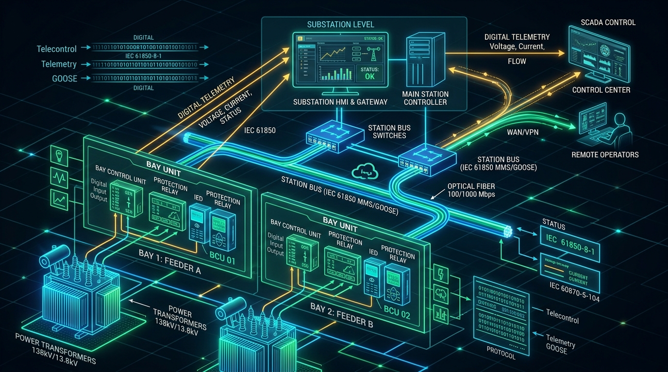
Figure 1: Cyber-physical layout of a modern automated electrical substation showing local control rooms and telemetry nodes.
System Architecture Hierarchy (IEC 61850)
Modern automated substations are modeled around three distinct physical and logical layers defined by the IEC 61850 standard. This separation ensures that safety-critical local operations can continue autonomously even if communication links to the upper-level SCADA servers are temporarily lost:
- Process Layer: The physical primary equipment located in the yard (substation switchgear, transformers, merging units, CTs, and VTs). This layer converts physical analog currents and voltages into high-speed digital sample values.
- Bay Layer: The local control room containing Intelligent Electronic Devices (IEDs), protection relays, metering devices, and Bay Control Units (BCUs). These devices run local protection algorithms (e.g. overcurrent, distance protection) and issue trip commands.
- Station Layer: The local human-machine interface (HMI), communication switches, local database servers, and the substation gateway. The gateway acts as the protocol converter, translating local LAN signals into WAN protocol streams for transmission to regional SCADA host centers.
To prevent software traffic from interference with hardware protection circuits, process-bus networks (between Process and Bay layers) are physically or logically isolated from station-bus networks (between Bay and Station layers) using VLAN tagging and managed industrial switches.
Figure 2: Substation Logical Control Flow
Process Layer
Physical instruments convert analog voltage/current to digital streams (Sampled Values).
Bay Layer
Intelligent relays (IEDs) analyze digital streams and execute local safety logic within 3ms.
Station Layer
Local HMIs display status and the Substation Gateway translates data to WAN SCADA protocols.
Protocol Integration & Latency Requirements
Different protocols govern communications inside and outside the substation boundaries. While local switchgear relies on ethernet multicast, WAN links use telecontrol protocols:
- GOOSE (Generic Object Oriented Substation Events): Defined under IEC 61850 for high-speed bay-to-bay interlocking and breaker trip signals. It bypasses TCP/IP layers to write ethernet frames directly, achieving safety-critical transmission times of less than 3 milliseconds.
- DNP3 / IEC 60870-5-104: Protocols used for remote master-to-outstation WAN telecontrol. DNP3 runs over TCP/IP (using port 20000) and includes features like unsolicited reporting (Class 1/2/3 events) to optimize bandwidth utilization on low-speed satellite or cellular links.
Academic & Industry References
- International Electrotechnical Commission. (2018). IEC 61850: Communication Networks and Systems for Power Utility Automation. IEC.
- IEEE Power & Energy Society. (2012). IEEE Standard for Common Format for Transient Data (COMTRADE) for Power Systems. IEEE.
- McDonald, J. D. (Ed.). (2012). Electric Power Substations Engineering (3rd ed.). CRC Press.
- DNP Users Group. (2012). IEEE Std 1815-2012 (DNP3 Protocol Specification). IEEE.