In electrical power engineering, the safety of personnel and the protection of high-voltage substation equipment depend entirely on the performance of the grounding grid. A properly designed earthing grid provides a low-impedance path to dissipate lightning surges and short-circuit fault currents into the earth, ensuring that touch and step voltages remain strictly within human physiological safety limits specified by IEEE Std 80. This guide outlines the step-by-step mathematical and physical design procedure for substation grounding grids.
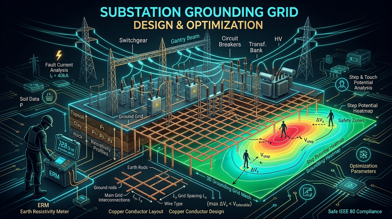
Figure 1: High-voltage substation grounding grid layout showing buried copper conductor mesh and surface crushed rock layer.
1. Soil Resistivity Measurement & Earth Modeling
The foundation of any grounding grid calculation is an accurate measurement of soil resistivity (ρ). Soil is rarely uniform; it consists of stratified geological layers with varying moisture content, chemical composition, and temperature.
Engineers utilize the Wenner Four-Pin Method (IEEE Std 81) to measure apparent resistivity across multiple electrode pin spacings (a). By plotting apparent resistivity against pin spacing, soil data is mathematically inverted into a two-layer soil model characterized by upper layer resistivity (ρ1), lower layer resistivity (ρ2), and upper layer depth (h).
Safety calculations assume a 50 kg or 70 kg human body weight. The maximum allowable touch voltage (Etouch) and step voltage (Estep) are governed by the surface layer resistivity (ρs) and the reduction factor (Cs) of the surface crushed rock layer (typically 0.10m to 0.15m thickness).
Figure 2: IEEE Std 80 Grounding Grid Design Procedure
Soil Survey (Wenner)
Measure apparent soil resistivity (ρ) across variable pin spacings.
Conductor Sizing
Calculate minimum cross-section area (A_kcmil) for thermal fault withstand.
Mesh Voltage (Em)
Calculate maximum mesh and step voltages under peak fault current (Ig).
Safety Verification
Verify Em < Etouch and Es < Estep; add ground rods if limits are exceeded.
2. Conductor Thermal Sizing & Fault Current Distribution
Grounding conductors (annealed copper or copper-clad steel) must withstand symmetrical fault currents without fusing or weakening exothermic welds. The minimum conductor cross-sectional area in kcmil (A_kcmil) is calculated using the Onderdonk equation:
Where: I = Symmetrical fault current (kA), tf = Fault duration time (seconds), Tm = Maximum allowable conductor temperature (1083°C for copper), Ta = Ambient temperature (°C).
Academic & Industry References
- IEEE Power & Energy Society. (2013). IEEE Std 80-2013: IEEE Guide for Safety in AC Substation Grounding. IEEE.
- IEEE. (2012). IEEE Std 81-2012: IEEE Guide for Measuring Earth Resistivity, Ground Impedance, and Earth Surface Potentials. IEEE.
- Sverak, J. G. (1981). Simplified Analysis of Electrical Grids Submerged in Two-Layer Earth. IEEE Transactions on Power Apparatus and Systems.