High-voltage circuit breakers are the critical safety valves of electrical substation networks, designed to isolate massive electrical faults within milliseconds to prevent grid blackouts and catastrophic transformer damage. Operating under harsh environmental conditions, these heavy electro-mechanical assets demand rigorous diagnostic testing protocols to verify absolute mechanical and electrical integrity. This technical guide outlines standard procedures for SF6 gas density monitoring, contact timing analysis, dynamic resistance measurement (DRM), and control coil current signature testing.
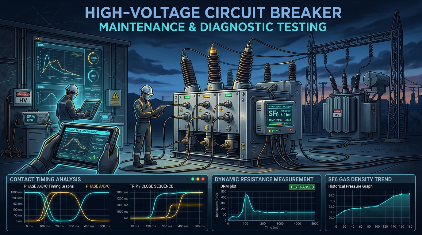
Figure 1: Maintenance crew performing contact timing and dynamic resistance testing on a substation SF6 circuit breaker.
1. SF6 Gas Density & Moisture Monitoring
Sulfur Hexafluoride (SF6) gas possesses exceptional dielectric strength and arc-quenching capabilities, making it the industry-standard insulating medium for high-voltage gas-insulated switchgear (GIS) and outdoor breakers. However, the dielectric performance of SF6 degrades severely if gas pressure drops or moisture content rises.
Moisture ingress combined with the extreme heat of electrical arcing generates toxic, corrosive decomposition byproducts (such as sulfur dioxide, hydrofluoric acid, and metal fluorides) that attack copper contacts and internal solid insulators. Diagnostic testing requires periodic gas sampling to measure dew point, purity, and decomposition levels, ensuring the gas remains within standard dielectric boundaries.
DRM injects a high DC current (typically 100A) during the breaker opening and closing stroke to measure contact resistance. By plotting resistance against contact travel distance, engineers can evaluate arcing contact length and erosion without physically opening the breaker.
Figure 2: Circuit Breaker Diagnostic Testing Sequence
SF6 Gas Analysis
Audit gas pressure, dew point moisture, and SO2 decomposition byproduct levels.
Contact Timing
Measure trip/close coil times, phase synchronicity, and mechanical contact bounce.
DRM Curve Audit
Plot dynamic resistance against stroke travel to assess arcing contact erosion.
Coil Signature
Record trip/close coil current signature to detect early mechanical binding.
2. Contact Timing Analysis & Phase Synchronicity
Breaker contacts must close and open within rigid, sub-cycle timing windows to isolate grid faults cleanly. Contact timing tests record close times, open times, and phase synchronicity (the time difference between the first and last phase poles closing, which should not exceed 2 milliseconds for high-voltage transmission networks). Mechanical bounce duration is also monitored, as excessive contact bounce creates severe transient surges and accelerate contact burn-out.
Academic & Industry References
- IEEE Power & Energy Society. (2009). IEEE Std C37.09-2009: IEEE Standard Test Procedure for AC High-Voltage Circuit Breakers Rated on a Symmetrical Current Basis. IEEE.
- CIGRE Working Group A3.06. (2004). Reliability of High Voltage Equipment: Final Report of the Second International Enquiry on Reliability of High Voltage Equipment in Service. CIGRE.
- International Electrotechnical Commission. (2020). IEC 62271-100: High-voltage switchgear and controlgear – Part 100: Alternating-current circuit-breakers. IEC.